DRZ400 Engine Rebuild

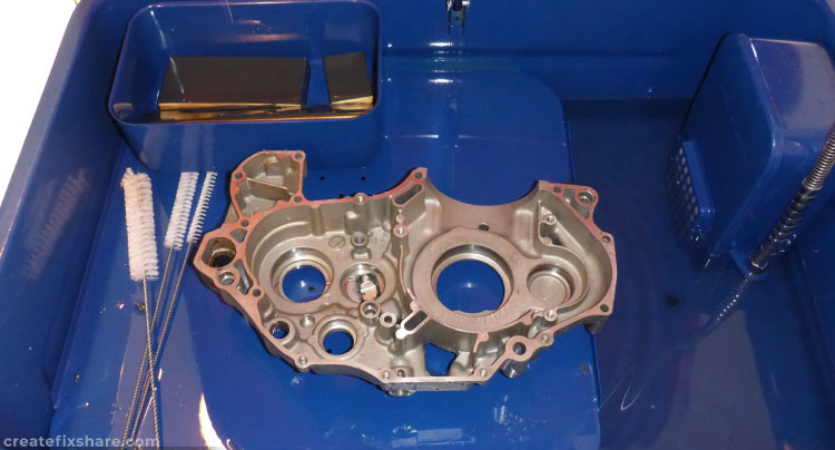
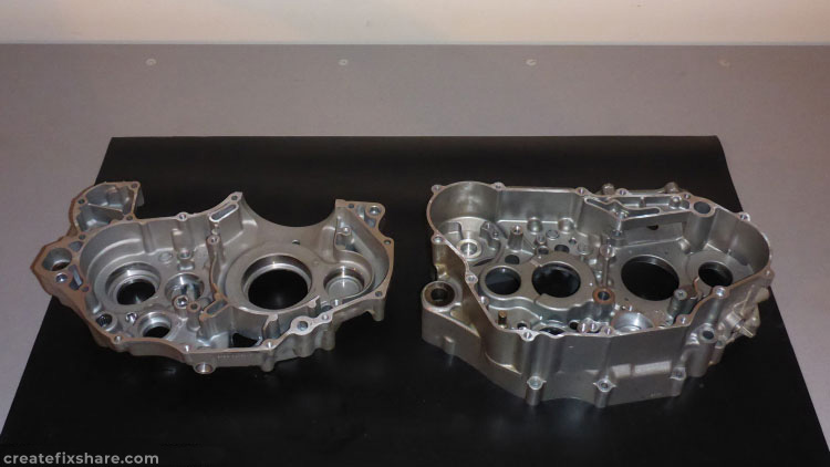
This article follows the process of a DRZ400 engine being rebuilt after running a bottom end bearing. It starts at the very beginning with cases apart. Because of running a bearing and potential metal contamination throughout the entire engine, the goal is to remove and replace all crankcase bearings. Following that it will be a process of dissemble, clean, inspect and measure every part subject to wear or that could potentially be harbouring contaminants.

This isn’t a comprehensive rebuild article with exact assembly sequences, torque specs etc, however it shows the majority of the steps and provides anyone interested in rebuilding a DRZ400 an excellent insight to the process.
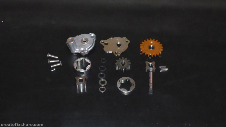
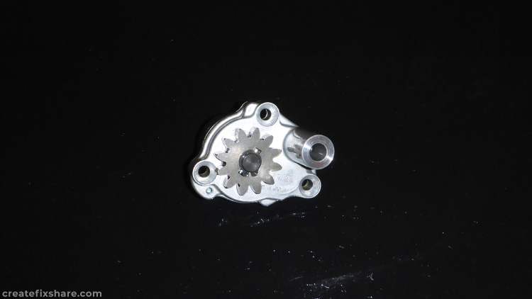
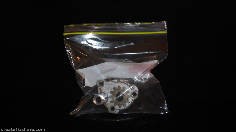
Photo 1 of DRZ400 Engine Rebuild
Washing up and cleaning surfaces of the left hand crankcase in the wash bath.
Photo 2 of DRZ400 Engine Rebuild
Both crankcase halves all washed up, all spic and span.
Photo 3 of DRZ400 Engine Rebuild
Crankcases wrapped and set aside ready for installing bearings.

Oil Pump

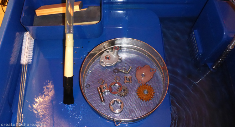
After cleaning up the cases the transmission was next but I was waiting for new input and output shaft circlips so it was onto the oil pump. This was disassembled, washed, inspected for wear and then reassembled.
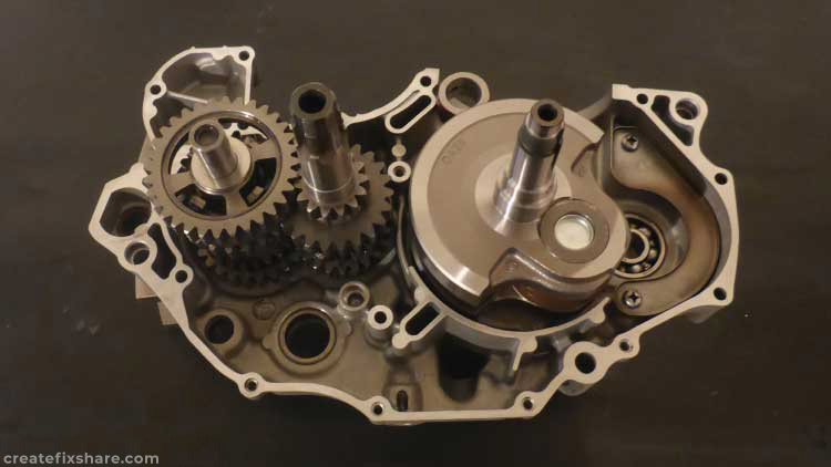
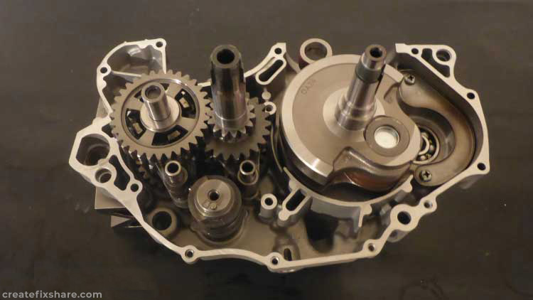
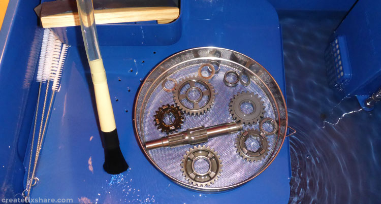
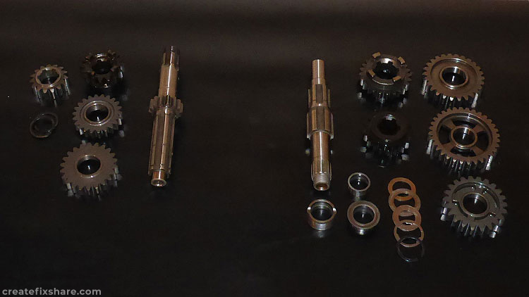
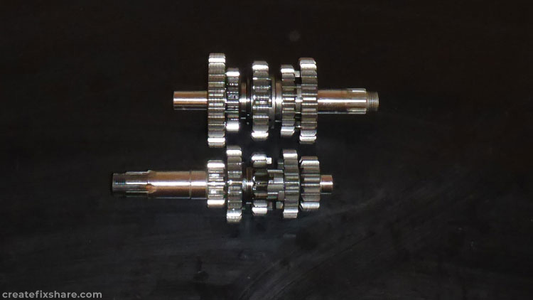
DRZ400 Oil Pump
Photo 4 of DRZ400 Engine Rebuild
Washing up all of the oil pump parts.
Photo 5 of DRZ400 Engine Rebuild
Inspecting oil pump parts for wear with a positive result of all parts being in good condition.
Photo 6 of DRZ400 Engine Rebuild
Oil pump lubed up, new circlips and assembled.
Photo 7 of DRZ400 Engine Rebuild
Bagged up and ready for assembly.

Transmission

With a parts delivery from Mr Suzuki which included the transmission shafts' circlips it was into the wash bath, clean, inspect, measure and reassemble.
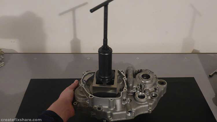
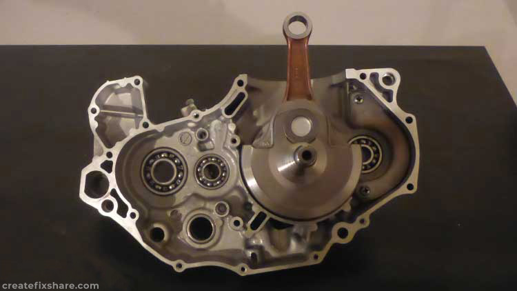
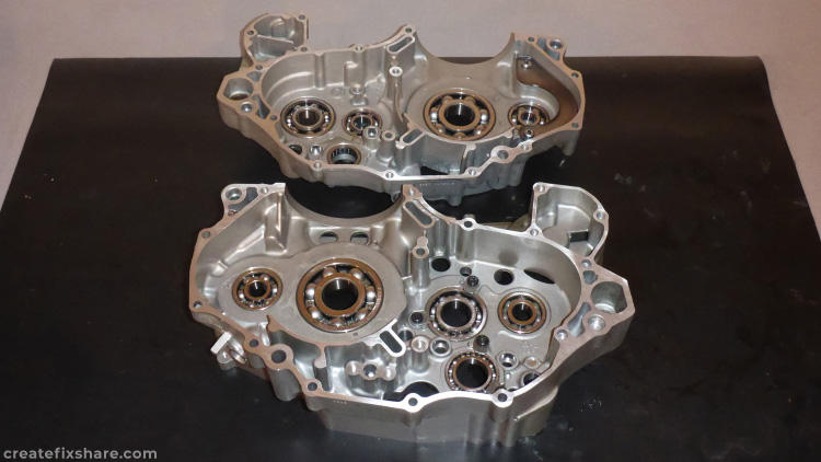
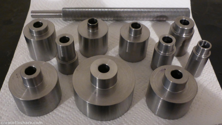
Photo 8 of DRZ400 Engine Rebuild
Washing up the output shaft and gears followed by the input shaft.
Photo 9 of DRZ400 Engine Rebuild
Cleaned, inspected and measured. All was within spec.
Photo 10 of DRZ400 Engine Rebuild
Lubed, assembled with new circlips and ready to roll.

New Engine Bearings

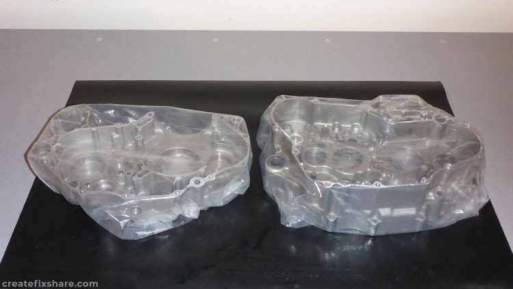
With a package arriving with the set of engine bearings, it was onto installing them. The cases were heated to 80 degrees C and the bearings cooling to 5 degrees C so the combination of respective expansion/contraction provided minimal interference and easy installation.
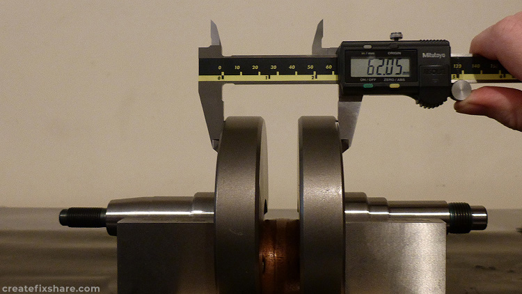
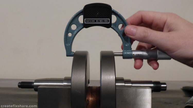
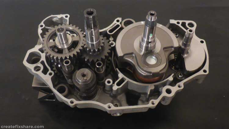
Photo 11 of DRZ400 Engine Rebuild
Engine cases fitted with the new engine bearings.
Photo 12 of DRZ400 Engine Rebuild
Although I have genuine Suzuki bearing removal/installer sets I opted to machine up my own set. This installer handle and set of attachments fits all the DRZ400 engine bearings plus the entire DRZ400 swingarm and linkage bearings. With a 12mm diameter hole these attachments can be used with either the punch handle or the Suzuki threaded bearing rod tool to press the bearings in.

DRZ400 Crankshaft

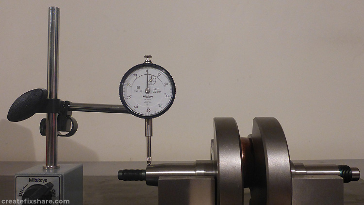
With the complete set of engine bearings in, next up was the crankshaft. The first task was to throw the crankshaft in some V blocks and check if the web to web measurements were within spec. This is really a test of, did any of the freighting companies drop it before it reached my doorstep! Following that it was the DTI test to check crank run-out.

Photo 13 of DRZ400 Engine Rebuild
First up was the initial check with some digital callipers. The Suzuki spec measurement to look for is 62.0 with a +/- of 0.1 mm. The measurements were within spec at 62.05 and consistent spanning around the webs.
Photo 14 of DRZ400 Engine Rebuild
Following this was the task of double checking the web to web with a micrometre. All the micrometre measurements agreed with the digital calipers.
Photo 15 of DRZ400 Engine Rebuild
The final test was crank run-out. In V blocks, the outermost ends were checked with a 0.01 DTI. The Suzuki max service limit is 0.08 which this crank breezed in at 0.015
Photo 16 of DRZ400 Engine Rebuild
Using a crank installer, the crank was pulled and seated into the crankcase bearing.
Photo 17 of DRZ400 Engine Rebuild
Seated crank.
Photo 18 of DRZ400 Engine Rebuild
Next up the input and output shafts were carefully slotted into place.
Photo 19 of DRZ400 Engine Rebuild
Following that was the gearshift cam and shifting forks. A quick test was performed to ensure the gearbox was operating normally before sliding in the counterbalance shaft.
Photo 20 of DRZ400 Engine Rebuild
Counterbalance shaft in place
Author of this article: RMOTO